Zeiss gom 3D Measuring Technology
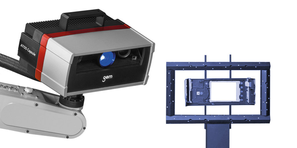
Due to its housing design, the ATOS Capsule provides process stability for automated applications. Made of plastic injection molding, the precisely manufactured unibody housing ensures maximum stiffness and precise measuring results for industrial use. Optics and electronics are protected against dust and splashing water.
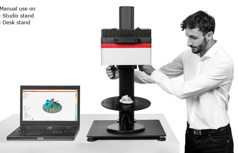
Optical 3D coordinate measuring machines are replacing tactile measuring systems and gages in many areas of industry. They capture more detailed and more easily interpretable quality information of an object with significantly shorter measuring times.
Whereas mechanical measuring systems capture data in a point-based or linear manner, optical measuring systems return full-field data about deviations between the actual 3D coordinates and the CAD data. As this measuring data contains all the object information, in addition to the surface deviations from the CAD, the software also automatically derives detailed information such as GD&T, trimming or hole positions.
Over 14,000 GOM measuring systems worldwide ensure the dimensional quality of automotive, sheet-metal, cast and injection molded products as well as turbine blades and wheels. In most cases, the detailed analyses are not used for a simple “OK”/ “not OK” evaluation, but rather form the basis for the optimization of production and machine parameters as part of a value-added measuring procedure.
- Highest precision (0.003mm)
- Smallest features
- Encapsulated optics
- Protected electronics
- Dustproof / splashproof
- Automation for small parts
To ensure precise measuring accuracy, the GOM software packages have been tested and certified by the two institutes PTB and NIST. The accuracy of the inspection software is confirmed by the comparison of the results obtained with the reference results. The GOM software has been placed in Category 1, the category with the smallest measurement deviations.
Actual-nominal comparison – The calculated polygon mesh describes free-form surfaces and standard geometries. These can be compared with the drawing or directly with the CAD data set with the help of a surface comparison. A 3D analysis of surfaces as well as a 2D analysis of sections or points can be implemented in the software. CAD-based generation of standard geometries such as lines, planes, circles or cylinders is also possible.
Alignment – The GOM 3D software contains all standard alignment functions. These include RPS alignment, hierar-chical alignment based on geometric elements, alignment in a local coordinate system,using reference points as well as various best-fit methods such as global best-fit and local best-fit. Customers can also use their own specific alignments, e. g. for turbine blades, such as balanced beam or equalized nested.
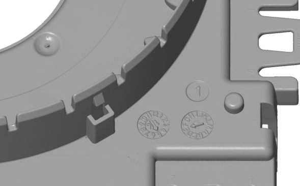
Surface defect map – The function detects small defects and visualizes e. g. dents or sink marks. To visualize and quantify local bulges and depressions, the surface defect map directly works on meshes. By comparing the nominal and actual surface inspection, the new feature allows the compensation of global curvatures.
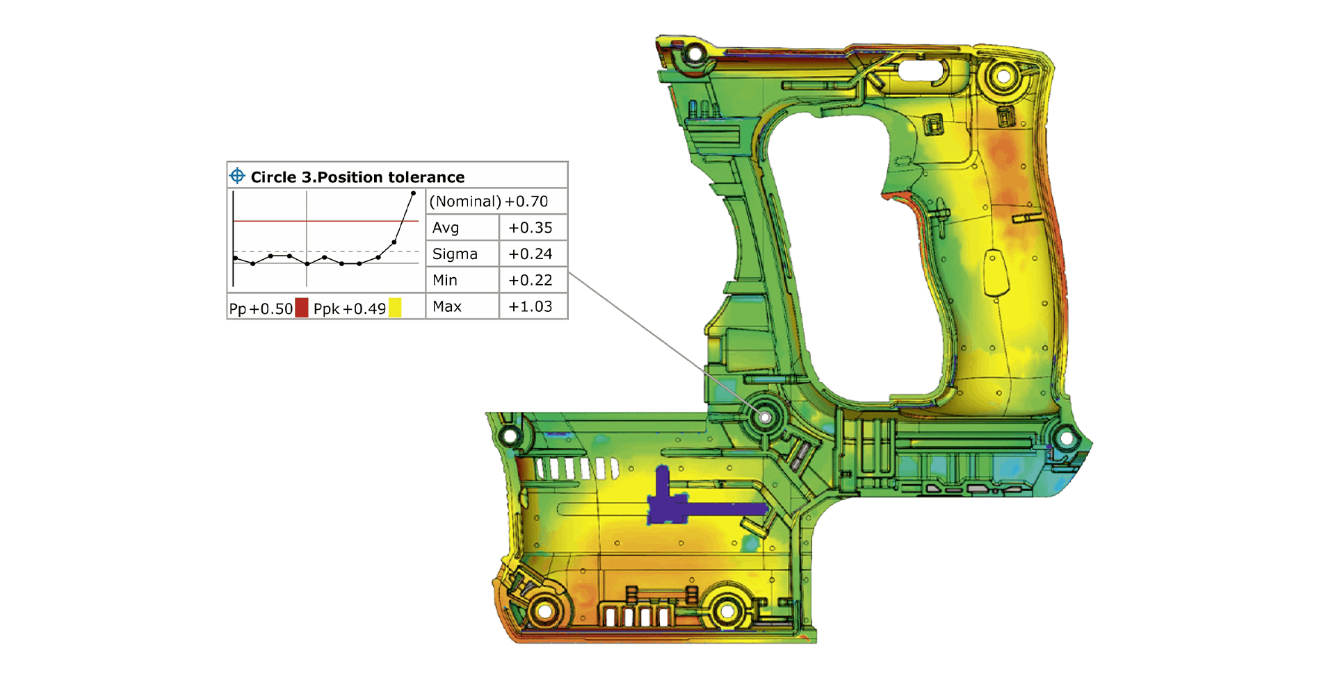
Trend, SPC and deformation analysis – The parameter-based approach of the GOM software enables trend analysis for multiple evaluation, e. g. for statistical process control (SPC) or deformation analysis. As a result, several parts or stages within a single project can be evaluated in a full-field manner, and statistical analysis values such as Cp, Cpk, Pp, Ppk, Min, Max, Avg and Sigma can be determined.
GD&T analysis – In contrast to the pure dimension analysis, the GD&T analysis focuses on the functional aspect of the part. Corresponding GD&T elements are, for example, planarity, parallelism or cylindricity. Both, a standardized analysis of 2-point distances and of the maximum mate-rial requirement as well as the position tolerance in local datum and coordinate systems are possible.
Airfoil inspection – Special functions are available for the quality control of turbine blades, which can be used, for example, to inspect the profile mean line, profile chord line or profile thickness of turbine blades on the basis of 2D sections. The profile centroid, profile radi and profile twists can also be calculated.
Reporting – The reporting module enables users to create reports containing snapshots, images, tables, diagrams, texts and graphics. The results can be visualized and edited in the user interface as well as exported as a PDF file. Templates are reusable, and each scene saved in a report can be restored in the 3D window.
Case study of applying optical 3D coordinate measuring technology to plastic injection parts
Case Background: A manufacturer specializing in automotive components was experiencing challenges with quality control and dimensional accuracy in their plastic injection-molded parts. These parts were critical components used in various vehicle systems, and even minor dimensional variations could lead to assembly issues and performance problems.
Problem Statement: The manufacturer faced difficulties in accurately measuring complex geometries, intricate features, and tight tolerances of the plastic injection-molded parts using traditional measurement methods such as calipers, micrometers, or CMMs (Coordinate Measuring Machines). Additionally, the time and labor required for manual inspection were significant bottlenecks in the production process.
Solution: To address these challenges, the manufacturer implemented optical 3D coordinate measuring technology, specifically structured light or laser scanning systems, for dimensional inspection of plastic injection-molded parts. They invested in a high-precision optical measurement system equipped with advanced software for automated data acquisition, analysis, and reporting.
Implementation:
-
System Setup: The optical 3D coordinate measuring system was installed in the quality control department adjacent to the injection molding facility. The system consisted of high-resolution cameras, structured light or laser projectors, and motion control systems for precise positioning.
-
Calibration: The measurement system underwent rigorous calibration procedures to ensure accurate and repeatable measurements. Calibration involved aligning the cameras, projectors, and motion control axes to a reference coordinate system with known accuracy.
-
Part Inspection: Plastic injection-molded parts were placed on the measurement stage or fixture, and the optical scanning process was initiated. The structured light or laser projection illuminated the part surface, capturing thousands of data points in a matter of seconds.
-
Data Processing: The acquired point cloud data were processed using specialized software to reconstruct the 3D geometry of the parts. Advanced algorithms were employed to align, merge, and analyze the data, enabling dimensional measurement, feature extraction, and surface analysis.
-
Dimensional Analysis: The software performed dimensional analysis by comparing the measured dimensions of the plastic parts against the CAD (Computer-Aided Design) model or nominal specifications. Deviations from the target dimensions were identified, and detailed reports were generated automatically.
-
Quality Assurance: The optical 3D coordinate measuring system enabled comprehensive quality assurance by detecting defects, variations, and deviations in the plastic injection-molded parts. Any out-of-spec parts were flagged for further investigation or rework.
Results: By implementing optical 3D coordinate measuring technology for plastic injection parts, the manufacturer achieved several benefits:
- Improved dimensional accuracy and consistency of injection-molded parts.
- Reduced inspection time and labor costs through automated measurement and analysis.
- Enhanced quality control capabilities, leading to fewer rejects and rework.
- Increased production efficiency and throughput by streamlining the inspection process.
Overall, the adoption of optical 3D coordinate measuring technology significantly enhanced the manufacturer's ability to ensure the quality and dimensional integrity of plastic injection-molded parts, contributing to customer satisfaction and competitiveness in the automotive industry.