Design

Mold Flow Analysis
All Plastic Solutions are Possible with us
First of all, many people think that if you know where to gate the part, you do not need to perform the mold flow analysis. That is a misconception and may not really help you that much in reducing costs and timing as well as may not prevent other problems. Yes you will be able to fill the parts and get the parts but will the parts be the best in very first tryout? That is a question that can be answered by performing the flow analysis.
Many times you many know the overall gate region on the part but you may not be able to locate the exact gate location to have a completely balanced fill all around the part and cavities. Such slight imbalance of 2-10% can be enough to create enough molding problems that sometime can not be seen in processing but are hidden in longer cycle time, cooling, packing issues, scrap rates, surface quality, gate or flow lines, surface finish, processing window, clamp tonnage. In today’s competitive market, this may be enough to wipe out your margins and profits. When you perform analysis from a expert source like Ideal Tech, Inc. then you not only will be able to avoid such issues but also improve your products and save cost and timing. This could be enough to add more to your pockets in the long term making your company more competitive yet producing better quality.
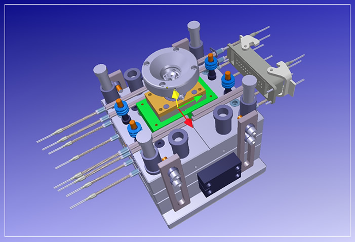
Molds design serviecs
-
Part Design Analysis: Understand the requirements and constraints of the final molded part. Analyze part geometry, functional requirements, material selection, and aesthetic considerations. Ensure that the part design is suitable for injection molding and can be efficiently manufactured.
-
Gate Design: Determine the location, size, and type of gate(s) for injecting molten plastic into the mold cavity. Select gate locations that minimize flow distance, reduce weld lines, and facilitate proper material distribution. Common gate types include edge gates, pin gates, and hot runner systems.
-
Runner System: Design the runner system to deliver molten plastic from the injection unit to the mold cavity efficiently. Consider factors such as flow rate, pressure drop, balancing, and cooling. Optimize runner layout, diameter, and length to minimize waste and cycle time.
-
Cooling System: Design an effective cooling system to dissipate heat from the mold cavity and core. Ensure uniform cooling to prevent warpage, shrinkage, and internal stresses in the molded parts. Incorporate cooling channels close to the cavity surface and use conformal cooling techniques for complex geometries.
-
Parting Line and Mold Split: Determine the parting line where the mold halves will separate. Design the mold split to facilitate easy ejection of the molded part and minimize mold complexity. Incorporate features such as slides, lifters, and inserts as needed for undercuts and complex geometries.
-
Draft Angle: Apply draft angles to the part design to facilitate mold release and prevent undercutting. Ensure sufficient draft angle on vertical surfaces to allow easy ejection of the part from the mold cavity. Typically, 1-2 degrees of draft angle per side is recommended.
-
Surface Finish and Texture: Specify the desired surface finish and texture for the molded part. Design the mold cavity and core accordingly to achieve the required surface quality, whether smooth, textured, or patterned. Consider factors such as part aesthetics, functionality, and demolding requirements.
-
Venting: Provide adequate venting throughout the mold cavity to allow air and gases to escape during the injection process. Prevent air traps, voids, and burn marks by incorporating vent grooves, micro-vents, or ejector pins strategically along the parting line and in areas prone to air entrapment.
-
Ejection System: Design an effective ejection system to remove the molded part from the mold cavity after solidification. Use ejector pins, ejector sleeves, or hydraulic ejectors to facilitate part release without damaging the mold or the part.
-
Tooling Considerations: Consider tooling constraints such as mold size, complexity, and manufacturability. Optimize mold design for efficient fabrication, assembly, and maintenance. Minimize tooling costs and lead times while ensuring high precision and durability.
-
Simulation and Analysis: Utilize mold flow analysis software to simulate the injection molding process and predict potential issues such as air traps, weld lines, and sink marks. Optimize mold design based on simulation results to achieve optimal part quality and performance.
By incorporating these key elements into the plastic injection mold design, manufacturers can produce molds capable of producing high-quality, precise, and consistent molded parts with minimal defects and optimal efficiency.
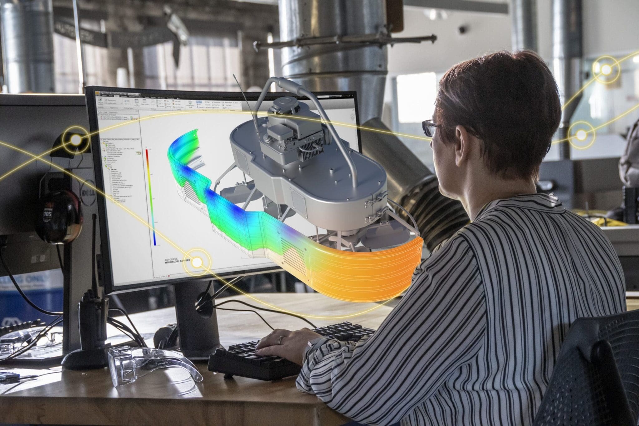
Mold Flow Analysis for Mold design optimization
Mold flow analysis is a critical tool used in the design and optimization of molds for injection molding processes. Here's how it works and why it's important:
-
Understanding Mold Flow: Mold flow analysis simulates the flow of molten plastic material within the mold cavity during the injection molding process. It predicts how the material will behave under different processing conditions, including flow patterns, pressure distribution, cooling rates, and potential defects.
-
Optimizing Design: By analyzing mold flow, designers can identify potential issues such as air traps, weld lines, sink marks, and warpage before the mold is manufactured. This allows for iterative design improvements to optimize part quality, minimize production defects, and enhance manufacturability.
-
Material Selection: Mold flow analysis helps in selecting the appropriate plastic material for the intended application by evaluating its rheological properties, melt temperature, viscosity, and flow behavior during injection molding. This ensures compatibility between the material and the mold design, leading to better part performance and consistency.
-
Gate and Runner Design: Mold flow analysis assists in optimizing gate and runner designs for efficient material flow and balanced filling of the mold cavity. It helps determine the optimal location, size, and geometry of gates and runners to minimize flow restrictions, reduce pressure drop, and prevent part defects such as short shots and flow hesitation.
-
Cooling System Design: Proper cooling is essential for achieving uniform part quality and minimizing cycle times in injection molding. Mold flow analysis allows designers to optimize the layout of cooling channels within the mold, ensuring optimal cooling rates and uniform temperature distribution across the part geometry. This helps prevent warpage, shrinkage, and residual stresses in the molded parts.
-
Predicting Part Behavior: Mold flow analysis provides insights into how the molded part will behave after demolding, including dimensional accuracy, shrinkage, warpage, and residual stresses. By simulating the cooling and solidification process, designers can anticipate and mitigate potential issues that may arise during production or in the final application.
-
Iterative Improvement: Mold flow analysis facilitates an iterative design process where designers can quickly evaluate multiple design iterations, assess their impact on part quality and manufacturability, and make informed decisions to optimize the mold design before fabrication. This iterative approach saves time and cost by minimizing the need for physical prototypes and trial-and-error testing.
-
Reducing Time-to-Market: By accurately predicting and addressing potential molding issues upfront, mold flow analysis helps streamline the product development cycle and accelerate time-to-market for new products. It enables designers to proactively identify and resolve manufacturing challenges early in the design phase, leading to faster and more cost-effective production ramp-up.
In summary, mold flow analysis is an indispensable tool for mold design optimization, helping designers achieve better part quality, higher production efficiency, and reduced time-to-market in injection molding processes.
Mold Materials Used in Plastic Injection Molding
Injection molding is a highly versatile manufacturing process used to produce a wide range of plastic parts and products. The choice of mold material is crucial as it directly impacts the quality, durability, and cost-effectiveness of the molding process. Here are some commonly used mold materials in injection molding:
-
Steel Alloys:
- Tool Steel (e.g., P20, H13): Tool steels are widely used for injection molds due to their excellent wear resistance, toughness, and machinability. P20 is a versatile, general-purpose tool steel suitable for many applications, while H13 offers higher hardness and heat resistance, making it suitable for high-volume production and molding of abrasive materials.
-
Stainless Steel:
- SUS 420, SUS 316: Stainless steel molds offer good corrosion resistance and are suitable for molding corrosive or high-temperature materials. SUS 420 is commonly used for general-purpose molding applications, while SUS 316 provides higher corrosion resistance, making it suitable for molding medical or food-grade plastics.
-
Aluminum Alloys:
- Aluminum 7075, Aluminum 6061: Aluminum molds are lightweight and offer excellent thermal conductivity, allowing for faster cooling and shorter cycle times. Aluminum 7075 is a high-strength alloy suitable for high-volume production, while Aluminum 6061 is more cost-effective and suitable for prototype or low-volume molding.
-
Beryllium Copper:
- C17200 (Alloy 25): Beryllium copper molds offer superior thermal conductivity and high strength, allowing for fast heat transfer and reduced cycle times. They are commonly used for molding thin-walled or intricate parts that require rapid cooling.
-
Pre-hardened Steel:
- NAK80, 718: Pre-hardened steels offer good machinability and dimensional stability, eliminating the need for post-machining heat treatment. NAK80 is a popular choice for molding optical and electronic parts, while 718 provides higher hardness and wear resistance, suitable for molding abrasive materials.
-
Tooling Resins and Composites:
- Epoxy Tooling Board, RenShape: Tooling resins and composites are used to create prototype or short-run molds quickly and cost-effectively. Epoxy tooling boards offer good dimensional stability and surface finish, while RenShape is a lightweight, machinable material suitable for creating complex molds.
The selection of mold material depends on factors such as part complexity, production volume, material compatibility, surface finish requirements, and budget constraints. Engineers and mold designers carefully evaluate these factors to choose the most suitable mold material for each specific application, ensuring optimal performance and cost-effectiveness in the injection molding process.
Types of Plastic Injection Molds
Plastic injection molds are essential tools in the manufacturing process of plastic parts. They come in various types, each designed for specific applications and production requirements. Here are some common types of plastic injection molds:
-
Two-Plate Mold: A two-plate mold, as the name suggests, consists of two main plates: the cavity plate and the core plate. These plates are mounted on the stationary and moving sides of the injection molding machine, respectively. The cavity plate contains the cavity, which forms the external shape of the molded part, while the core plate contains the core, which shapes the internal features of the part.
In a two-plate mold, the cavity and core are aligned to create a complete mold cavity when closed. Molten plastic is injected into this cavity, filling the space and taking the shape of the mold. Once the plastic has cooled and solidified, the mold opens, and the part is ejected.
Two-plate molds are relatively simple in design and construction, making them cost-effective and suitable for a wide range of applications. However, they may not be suitable for parts with complex geometries or features that require side-action mechanisms.
-
Three-Plate Mold: A three-plate mold is more complex than a two-plate mold and consists of three main plates: the cavity plate, the core plate, and a third plate known as the runner plate or the stripper plate. The runner plate sits between the cavity and core plates and contains channels (runners) that guide molten plastic from the injection nozzle to the mold cavity.
In a three-plate mold, the runner plate serves to separate the sprue, runners, and gates from the molded part, allowing for easier ejection. When the mold opens, the runner plate moves independently from the cavity and core plates, facilitating the removal of the sprue and runners.
Three-plate molds are often used in applications where gating and runner design are critical, such as multi-cavity molds or molds with complex runner systems. They offer more flexibility in gating locations and can help minimize waste by allowing for the recycling of runner material.
-
Single Cavity Molds: Single cavity molds produce one part per cycle. They are suitable for low-volume production or for large parts where multiple cavities would be impractical. Single cavity molds are often used for prototyping or small-scale manufacturing.
-
Multi-Cavity Molds: Multi-cavity molds have two or more identical cavities, allowing for the simultaneous production of multiple parts in each molding cycle. They are used to increase production efficiency and reduce unit costs for high-volume manufacturing. Multi-cavity molds are commonly employed in industries such as automotive, electronics, and consumer goods.
-
Family Molds: Family molds consist of multiple cavities, each producing different parts simultaneously. This allows for the production of assemblies or sets of parts in a single molding cycle, streamlining manufacturing processes and reducing production time and costs. Family molds are beneficial for producing components that are assembled together in the final product.
-
Hot Runner Molds: Hot runner molds utilize a system of heated channels to deliver molten plastic directly to the mold cavity, eliminating the need for runners and reducing material waste. They are ideal for high-volume production where fast cycle times and minimal material waste are crucial. Hot runner molds are commonly used in industries such as packaging, medical devices, and consumer electronics.
-
Cold Runner Molds: Cold runner molds feature a system of unheated channels (runners) that deliver molten plastic from the injection unit to the mold cavity. After each cycle, the excess material in the runners must be removed, resulting in some material waste. Cold runner molds are often used for lower volume production or when hot runners are not feasible due to material requirements or cost considerations.
-
Insert Molds: Insert molds incorporate metal or plastic inserts into the mold cavity before injection, allowing for the encapsulation of pre-formed components or inserts within the molded part. They are used to produce parts with integrated features or to improve part strength and functionality. Insert molds are commonly employed in industries such as automotive, aerospace, and electronics.
-
Overmolding/Two-Shot Molds: Overmolding or two-shot molds enable the injection of multiple materials or colors into the same mold to create parts with multiple layers or components. They are commonly used to produce soft-touch grips, multi-color parts, or parts with integrated seals or gaskets. Overmolding is often utilized in industries such as consumer electronics, medical devices, and household appliances.
-
Prototype Molds: Prototype molds are used to produce low-cost prototypes or small quantities of parts for testing and validation purposes. They are often made from less expensive materials and may have simplified designs compared to production molds. Prototype molds are essential for product development and iteration processes in industries such as consumer products, industrial equipment, and medical devices.
These are some of the primary types of plastic injection molds used in manufacturing. The selection of the appropriate mold type depends on factors such as production volume, part complexity, material requirements, and cost considerations.